
Experiment no: 01
Name of the Experiments: Demonstration on Closed-loop Inverting And Non- inverting Amplifier characteristics.
Objective: This experiment is intended to observe the application of Op-Amp IC as Inverting and Non- inverting Amplifier.
Apparatus:
1. Digital Multimeter
2. Signal Generator
3. Oscilloscope
4. Trainer board
5. Connecting wires
6. Op-amp IC( LM 351/ μA741)
7. Resistors
8. Power supply
Theory: Inverting Amplifier
For close-loop inverting amplifier as shown in figure 1.1, the input voltage is applied to the inverting terminal of the op-amp and negative feedback is applied. The output voltage is feeding back to the inverting terminal of the op-amp via the feedback resistor, RF. The non-inverting terminal is grounded, and an extra resistor R1 is connected in series with the input signal source vin. However, the difference input voltage is ideally zero; the voltage at the non-inverting terminal (v2) is approximately equal to that at the non-inverting terminal (v1).
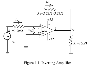
In other words, the inverting terminal voltage v2 is approximately at ground potential. Therefore, the inverting terminal is said to be at virtual ground. In the circuit of figure 1.1,


Procedure:
1. Construct the circuit as shown in the figure-1.1
2. Determine the values of different resistors and the gain AF.
3. Calibrate the oscilloscope and take input signals from the signal generator and also adjust the amplitude and frequency.
a) When vin(dc)=3V ,
(i) Determine the output voltage, vo
(ii) Determine the output current, Io by applying Ohm’s Law.
(iii) Calculate the theoretical output voltage, vo.
(iv) Calculate the % of error for vo using the formula-
b) When vin(ac)=3VPeak at the frequency of 1kHz.
(i) Sketch vo and vin with respect to time.
(ii) Determine the output current, Io by applying Ohm’s Law.
(iii) Calculate the theoretical output voltage, vo
(iv) Calculate the % of error.
4. Measure the saturation time duration if saturations occur from the oscilloscope and also
calculate the saturation time.
5. Replace RF by another resistor of different value, and repeat the above instructions again
and complete the data table- 1.1 given below.


Procedure:
1. Construct the circuit as shown in the figure-1.2.
2. Determine the values of different resistors and the gain AF.
3. Calibrate the oscilloscope and take input signals from the signal generator and also adjust the amplitude and frequency.
(a) When vin(dc)=3V ,
(i) Determine the output voltage, vo
(ii) Determine the output current, Io by applying Ohm’s Law.
(iii) Calculate the theoretical output voltage, vo.
(iv) Calculate the % of error for vo using the formula
(b) When vin(ac)=3VPeak at the frequency of 500 Hz.
(i) Sketch vo and vin with respect to time.
(ii) Determine the output current, Io by applying Ohm’s Law.
(iii) Calculate the theoretical output voltage, vo
(iv) Calculate the % of error for vo.
4. Measure the saturation time duration if saturations occur from the oscilloscope and also calculate the saturation time.
5. Replace RF by another resistor of different value, and repeat the above instructions again and complete the data table-1.2 given below.

Conclusion
In this experiment we learned how to properly build various circuits using op-amp. We can build various types of circuits, adders and amplifiers are the most simple ones among them. Here we also learned the basic pin layout of an op-amp and saw and that amps can intaed work as both as adder and an amplifier.
Thank you.
More contain Follow.


0 Comments