
Introduction:
You know that positive reactive power is needed to create the magnetic field in an alternating current motor. This reactive power has the disadvantage of producing a low power factor. Low power factors are undesirable for several reasons. Generators, Transformers and supply circuits are limited in rating by their current carrying capacities. This means that the kilowatt load that they can deliver is directly proportional to the power factor of the loads that they supply. For example, a system can deliver only 70% of the kilowatt load at 0.7 power factor that it can deliver at unity power factor. The Synchronous motor requires considerable reactive power when it operates at no-load without any DC excitation to the rotor. It acts like a three-phase inductance load on the power line. When the rotor is excited, it will produce some of the magnetism in the motor with the result that the stator has no supply less, and the reactive power drawn from the power line decreases. If the rotor is excited until it produces all the magnetism, the power line will only have no supply active power to the stator, and the power factor will be unity. As far as the power line is connected, the Synchronous motor now looks like a three-phase resistance load. If the rotor is excited still further, tending to create more magnetism than the motor needs, then the power line starts supplying negative reactive power to the stator in its attempt to keep the total flux constant. But negative reactive power corresponds to a capacitor, and the Synchronous motor now looks like a three-phase capacitance load to the power line.
An no-load, the Synchronous motor has the property of acting like a variable inductor/ variable capacitor, the value of reactance (XL or XC ) being determined by the amount of DC current flowing in the rotor. A Synchronous motor when used on the same power system with induction motors improves the overall system power factor.
Starting of synchronous machines:
A synchronous machine does not possess starting torque but once brought near to synchronous speed, it is capable of developing torque. Synchronous machine can be started either by means of some auxiliary machine coupled to its shaft or by running it as an induction machine till it attains a speed near to the synchronous speed. Usually starting synchronous machines as an induction motor is quite common. In this case, the field circuit of the synchronous machine is closed through high resistance and reduced voltage is applied across the stator windings. Due to three-phase balanced supply into the windings of the stator a rotating magnetic field is set up which rotates at synchronous speed. This rotating field interlinks with the damper winding (short circuited copper grids placed on the pole shoes), which behaves just like the squirrel cage rotor of an induction motor. Thus the motor starts as an induction motor in the direction of rotating field and comes to full speed which is slightly less than synchronous speed and field circuit of the synchronous machine can be connected to the D.C. supply. During starting, the field winding is closed through high resistance to reduce the current in the field winding.
Apparatus:
1. Power Supply Unit
2. Synchronous motor
3. AC Voltmeter
4. AC Ammeter
5. DC Ammeter
Circuit Diagram:

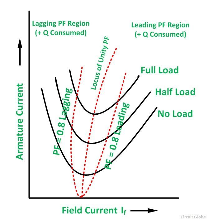
Synchronous Motor V curve compressor:
Procedure:
- Using the 10-hp motor-generator set (DC-AC) that you used in the Alternator Synchronization experiment, design an experiment to obtain the V-curve for a lightly loaded synchronous machine.
- Your design should include a diagram to measure the three-phase power supplied to the AC motor using the available connecters and equipment.
- Drive a dc generator with a wye-connected synchronous motor. Arrange to measure watts, volts and amperes at the motor input, the field current of the motor, and V and I at the DC generator output.
- Observe the ratings of the motor, the DC generator, and the load, then decide on a few input power levels to which you will obtain the V-curves.
- Change the field current of the synchronous motor and measure If and Ia. Observe when Ia becomes minimum and take a few readings above and below this minimum value.
- Switch off the supply to the motor and connect a resistive load to the DC generator.
- Change the power input to the synchronous motor by changing the resistive load and/or the field rheostat of the field circuit of the DC generator.
- For each load, measure the input power, the input current, the field current of the motor, the output DC current and voltage.
Report:
Discussion:
When load is applied to a synchronous machine, the machine poles fall back a certain angle δ behind the forward rotating poles of the stator. The value of this angle depends upon the load power factor and the excitation of the machine.


0 Comments